Until about the early 1900s (don’t quote me on that), many boats were powered by paddle wheels. That’s not too important.
The efficiency of a paddle wheel is increased when the individual paddles remain upright the entire time they’re in the water. One way of doing this is with a vertical bucket paddle wheel, which uses a second, offset wheel to maintain the paddles’ orientation.
The mechanism was deemed cool enough by me to bother modelling it:
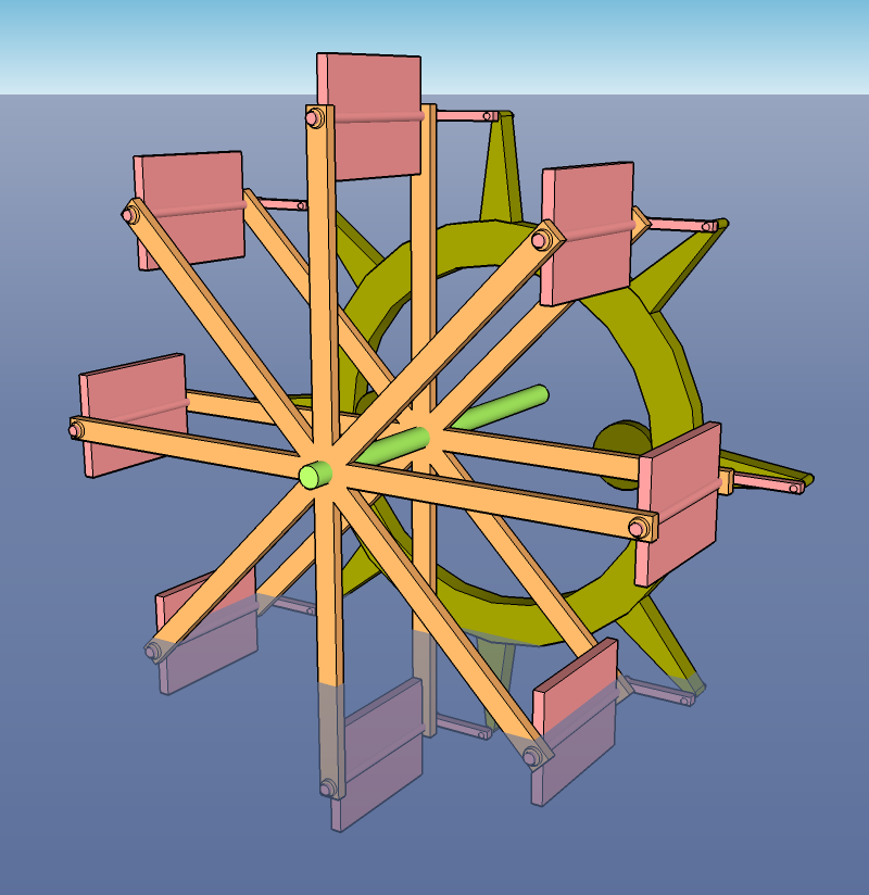
At least, approximately. There’s not much information to go by, all I had was this page which is also where I even heard about it. So what you see above is more my take on the mechanism.
The main difficulty arises from how the paddles have to stay in the same position all the way around. So for instance, if the part joining them to the green wheel were in the centre, then the connection would bash into the orange spokes. It’s also not possible to place the green wheel on any sort of axis, as any connections from there to the perimeter would bash into the light green axis.
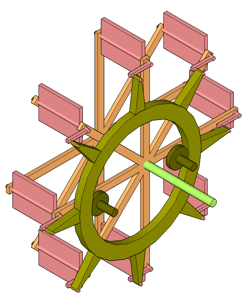
Although now that I think about it, it would be possible to power the green wheel, not the orange one, and then the axis of the orange wheel could stick into the hull of the ship, supported but not actually going through the green wheel. The orange one wouldn’t be so well supported in that case, but that depends on how far back the green one goes.
Regardless, the method I used was to support it on two small darker green rollers within the circumference. I ought to find some different CAD software that lets me animate stuff, because that’s always nice.
I think it’s pretty cool. If I ever find myself drawing a paddle steamer or something similar, I’ll probably do the wheels like this.
No comments found.